Hans Mikelson
Printer friendly
sampler.orc sampler.sco sampler2.sco whist0.wav whist1.wav whist2.wav
Introduction
This article describes how to implement a sampler using Csound. I use the term sampler to mean an instrument which generates sound by playing back recorded samples of other musical instruments or sounds. Instead of using one of the preexisting opcodes which simplify sampling like loscil I have decided to use the simpler oscil opcode. I have chosen to do this for two reasons. One: it gives you a feeling for what goes on behind the scenes in a sample player. Two: the loscil opcode is reputed to be somewhat problematic.
History
Some other samplers of historical significance include the Mellotron, the Emu Emulator, the Casio SK-1 and the Korg M1. It was perhaps the Korg M1 synthesizer that established the sample player workstation as the dominant form of synthesizer throughout the 1980's and most of the 1990's.
Tin Whistle
The sample set I have created is based on a penny whistle. For the first sample I scoop into the pitch at a low volume. For the second sample I play normally and for the third sample blow hard at the beginning to add an octave higher chirp to the attack.
Creating the Samples
Here are some tips for those who have never created samples before. I recorded the whistle samples into my computer using a Shure SM57 microphone going through a mixer then into a Soundblaster Live card. I used CoolEdit sample editing software to work with them once I had captured them.
It may take some experimentation to get a good sound. I usually record a large number of individual notes at slightly different volumes, different distances from the microphone, and different positions of the instrument with respect to the microphone. I usually record these all as one big sample and then listen to it to see which samples sound the best. Be sure to leave a long enough space between each note to make it easy to work with them later.
I try get the amplitude of the sound to be fairly constant and to be as loud as possible without clipping. Sometimes I run a noise reduction program to remove any noise from the sample. Note that this can alter the sound of the sample slightly. The noise reduction program needs a little ambient noise to work with so I do not trim the ends of the sample until after I have done noise reduction. After noise reduction I trim off silent sections from the beginning and end of the sample using a sample editor. Trimming any blank space from the beginning of the sample makes it more responsive when played and trimming blank space from the end makes it take up less memory.
Finding the Loops
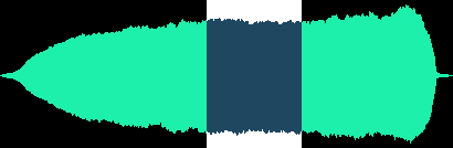
Once I had some samples that seemed to sound fairly good I had to determine where to put the loop points. Finding good sounding loops is beyond the scope of this article but I will try to give a couple of tips to get you started if you are just beginning. First of all look at the over all shape or envelope of the sound. Choose your loop points in a region of the sound that is fairly constant in magnitude as can be seen in the following image:
Next I zoom in and look for a good place to position the loop point.
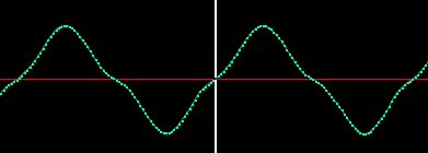
I like to choose a position where the slope is small and near a zero crossing. I like to choose the final loop point at a sample slightly below zero and the initial loop point slightly above zero. That way when it wraps around the sound will hopefully be continuous and without clicks. Next you need to listen to the sound and see if you can not tell where the loop is. I also try to find waveforms that look similar in appearance. You should also try to choose loop points that have the some harmonic content that is the same number of high and low frequencies. Once you have determined the sample points you are ready to set up your instruments.
For this example I created two instruments. A standard instrument triggered from a conventional score and a MIDI instrument which can be played from a MIDI keyboard.
The Table Table
I place all the information pertaining to the samples in a table itd.
; SampData	Table	RootFq	TabSz	Loopi	Loopf
f12 0 8 -2	2 	586	131072	38061	55335
f13 0 8 -2	3	586	131072	24738	69096
f14 0 8 -2	4	586	131072	9783	67937
This includes the root frequency of the sound, the size of the table holding the sample, and the loop initial and final samples. The orchestra reads this information as follows:
itab table 0,itd ; Sample table
ibfq table 1,itd ; Base frequency
itsz table 2,itd ; Table size
ilpi table 3,itd ; Loop start
ilpf table 4,itd ; Loop end
Tuning in the Right Frequency
I next calculate a factor used to adjust the frequency, ifadj.
ifadj = sr*ifqc/ibfq	; sr/TableSize is 1/Time to read table once at sr,
; next adjust fqc/basefqc
This factor shows up a few times in the following calculations so I pre-calculate it here to try and save some time. It is a correction factor for sample rate and base frequency of the sample. The base frequency of the sample is the pitch of the original recording.
Next I compute the loop duration in samples from the loop beginning, ilp, and ending, ilpf, locations.
ilpd = ilpf-ilpi
Envelopes & LFOs
I implement a declick envelope which is just a flat envelope with short attack and decay times. I made the decay a bit longer in order to simulate the character of the instrument. I use interp to interpolate between k-rate sets of samples because the linseg opcode generates some jagged lines when kr does not equal sr.
kdclk linseg 0,.002,1,idur-.022,1,.02,0 ; Declick
adclk interp kdclk
The first of the following two envelopes is used for the attack portion of the sample. After the appropriate attack time I cross-fade to the loop envelope, kenv2.
kenv1 linseg 1,ilpi/ifadj,1,.1,0,.01,0 ; Attack
kenv2 linseg 0,ilpi/ifadj,0,.1,1,.01,1 ; Loop
The following oscillator is used to generate vibrato. I apply an amplitude vibrato to the whistle sound. I this sounds better to me than using a sample with natural vibrato built in. If you have vibrato in the sample it changes speed unnaturally as you play different pitches.
kavib oscili .2,4,1 ; Sine amplitude vibrato
Set Your Phasors
aphs1 phasor ifadj/itsz ; Attack
This is the phasor for the attack. A phasor is like a sawtooth that ramps from 0 to 1 then jumps back to 0. The frequency of the phasor is the frequency adjustment number calculated earlier (ifadj) divided by the table size.
asig1 table3 aphs1,itab,1
I use a table3 here because it uses cubic interpolation. This makes the samples sound better when you are playing pitches that are not close to the recorded pitch of the sample. The last parameter, 1, causes the index mode to be 0-1 which is what we want with the phasor.
aphs2 phasor ifadj/ilpd,1-frac(ilpi/ilpd)
The phasor for the looped portion is a little tricker. We start off with the same frequency. As I ran this instrument I would get some drop out when the loop faded in. I determined this was due to the phase of the loop not matching the phase of the attack portion. This is because the loop is cycling during the attack even though you don't hear it because of the envelope. After some trial and error I found that 1 - the fractional part of (ilpi/ilpd) could be used to match up the loop phase with the attack phase.
asig2 table3 (aphs2*ilpd+ilpi)/itsz,itab,1
The phasor reading this table is modified so that it starts at the initial loop position, ilpi and and has an amplitude of the size of the loop. I then scale this by the size of the table, itsz so that it ends up scanning the loop portion of the table correctly.
Mix & Match
asigi = asig1*kenv1*.8
asigl = asig2*kenv2*(.8+kavib)

asig = asigi+asigl
The signals are mixed together and some amplitude vibrato is applied. A pitch vibrato could be generated with a delay line or in the phasor of the table. The problem with adding it into the phasor frequency though is that the attack and loop phases may get thrown off again slightly. Finally I declick the signal and send it out.
outs asig*iamp*adclk, asig*iamp*adclk
Tables 2 through 4 are for the three samples.
f2 0 131072 1 "whist0.wav" 0 0 0
f3 0 131072 1 "whist1.wav" 0 0 0
f4 0 131072 1 "whist2.wav" 0 0 0
Tables 12, 13 and 14 hold the information about the samples in particular the sample table number, the root frequency of the sample, the size of the table holding the sample and the loop beginning and ending samples.
; SampData Table RootFq TabSz  Loopi Loopf
f12 0 8 -2 2     586    131072 38061 55335
f13 0 8 -2 3     586    131072 24738 69096
f14 0 8 -2 4     586    131072 9783  67937
The call to play the instrument is now straightforward.
;  Sta Dur Amp   Pitch Table Pan
i1 0   .2  20000 9.02  13    .5
The second instrument applies the same concepts to a MIDI controlled instrument. This instrument can be played on from a MIDI keyboard. Converting an instrument for real-time use with MIDI is easy enough. First the velocity of the note is obtained using veloc. I then use a table to convert this to amplitudes. You can set up your table for different velocity sensitivity response curves. The cpsmidi opcode gets the the pitch of the midi note.
ivel veloc ; Velocity
iamp tablei ivel, 5 ; Convert to amplitude
ifqc cpsmidi ; Get the note in cps
The score now includes the following line:
f0 30 ; Runs for this many seconds
This allows the instrument to play for 30 seconds. In addition I am currently using the following command line with DirectCsound 5.1.
Conclusion
Hopefully this instrument was useful in understanding how to make a sample
player without relying on specialized opcodes. Generating good quality
samples and finding good loop points is the hardest part. Once these are
determined phasors are used to access the sample tables. The phasors are
adjusted so that the loop and attack portions remain in phase. Envelopes
are used to cross-fade between the attack and the loop. The MIDI specific
opcodes can be used to make the instrument playable from a MIDI keyboard.