Introduction
The GRM tools plug-in FreqWarp (part of the plug-in package "Spectral Transform Tools") is perhaps one of the most widely known and used implementations of frequency warping[1]. In fact, I have yet to find another frequency warping software tool that combines a decent sounding FFT algorithm with such a flexible and easy to use interface, as demonstrated by the FreqWarp plug-in. One could go as far as to say that this GRM plug-in is unique both in concept and execution: frequency warping as an abstract concept belongs to a rather obscure territory, with no single standard definition, DSP application or method of implementation. Given its highly esoteric character, an attempt to duplicate or implement this plug-in again in Csound may appear trivial and even uncreative at first.
Initially, this project started as a double challenge: first, to test and expand my ability at coding, and second, to examine the flexibility of Csound's PVS real-time spectral processing opcodes[2]. In addition, a GUI similar to that found in the GRM plug-in must be considered an indispensable part of this algorithm--it is crucial that the user can easily and coherently manipulate all the available FFT bins (e.g. 512 bins for an FFT size of 1024 samples) to arrive at the "warped" spectrum. Since Csound itself does not offer a table manipulation GUI widget, a third party language must be used to program the interface, and what better excuse to delve deeper into the possibilities offered by combining Csound and Max/MSP (using the external Max object csound~).[3]
I soon realized that a Csound/Max implementation can indeed compare well with the GRM tools plug-in. Furthermore, as the project evolved, more functions were added to the interface, expanding the possibilities offered by the GRM tools GUI (Figure 1). What follows in this article is a general description of the frequency warping method used by the GRM tools followed by a Csound implementation with Max based graphical interface. The reader is expected to be familiar with both Csound and Max (MSP is not discussed here), although the Max part can be ignored by those only interested in the core DSP engine of the program.
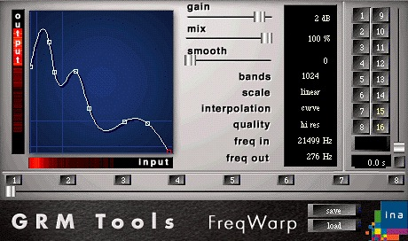
Figure 1: The GRM Tools graphical user interface.
FreqWarp
In principle this plug-in is rather simple. Its effectiveness is due to its ingeniously coherent interface, which allows the manipulation of the analyzed FFT data. As the picture above shows, the main part of the interface comprises of a function, drawn on an XY graph. This function represents and controls the remapping of the FFT data (frequency and amplitude). The horizontal axis (marked input) represents the original mapping of the analyzed signal with the bins arranges from zero to FFT size/2. The vertical axis represents the output bin destinations, to which the input bin's frequency and amplitude data are copied. Thus if the function is a straight line from zero to FFT size/2, the analyzed signal is synthesized again unaltered: input data for bin one is mapped to output bin 1, input data for bin 2 to output bin 2, and etc. This simple manipulation of the FFT data can yield highly radical results. In practice what the user influences is the amplitude or energy distribution of FFT bins across the full frequency range. For instance, by inverting the default function, one can invert the distribution of spectral energy in the output signal. Subtle manipulations will of course create more natural results. In short, the FreqWarp interface makes it possible to manipulate and tweak a highly abstract FFT algorithm in a perceptibly coherent manner.
The Csound Implementation
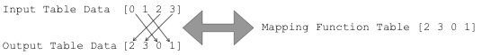
Glancing through the list of PVS opcode it is clear that no opcode exists to allow frequency warping as demonstrated by the GRM tools (see the above section). Here we need an opcode that can manipulate the index of the analyzed FFT bins in order to remap the FFT data, before sending it to the resynthesis engine. In other words we need to be able to write the analysis data to a table. This table is then read index by index, while each index is copied to a second table according to a mapping function given in a third table. This process must occur iteratively on each analyzed FFT window. The remapping operation is demonstrated below in Figure 2, using a hypothetical FFT size of 8 samples, which yields a total of 4 usable bins.
To write the PVS data generated by pvsanal opcode into a table we have at our disposal the pvsftw opcode. The table data can later be converted back into the PVS format using the pvsftr opcode. Below is a straight write/read operation without any intervening manipulation (writeReadTableFsig.csd).
instr 1
ifftsize = 2048 ;FFT size
iol = 4	    ;Overlap factor
ihop = ifftsize/iol	;hop size
iwindow = ifftsize*2	;window size (can be larger than FFT)
iwintype = 2
iNumBins = (ifftsize/2) + 1 ; The number of used bins+1
ifreq ftgen 0,0,iNumBins,2,0
iamp  ftgen 0,0,iNumBins,2,0

;function table for remapping the data
iwarpfunction ftgen 0,0,iNumBins,-7,0 ,iNumBins, iNumBins

ain1	in
ain1	dcblock	ain1
fsig1	pvsanal 	ain1, ifftsize, ihop, iwindow, iwintype
; export fsig amplitude and frequency data to table
kflag 	pvsftw fsig1, iamp, ifreq

if (kflag > 0) then ; only proc when frame is ready
; read data back to fsrc
	pvsftr fsig1, iamp, ifreq
endif

aout1 pvsynth fsig1
outs	aout1
endin
All that remains is an intermediary section in the code to allow manipulation of the table data. Following the spectral stretch model by Matt Ingalls, I decided to encapsulate all the table manipulations inside a UDO (user defined opcode) to simplify the code.[4] Thus the amplitude and frequency values contained in each FFT window are each written to a different table, which is in turn manipulated by the UDO with the following algorithm: starting from the first bin (at input table index 0), frequency and amplitude pairs (in ampin and freqin) are copied one by one into ampout and freqout at arbitrary index points defined by a fifth warping function table, which will later be accessed graphically in Max to allow a more intuitive data manipulation. The output tables ampout and freqout are then read by pvsftr, replacing the input tables. So our original code has to be altered as demonstrated below.
instr 1
ifftsize = 2048 ;FFT size
iol = 4	    ;Overlap factor
ihop = ifftsize/iol	;hop size
iwindow = ifftsize*2	;window size (can be larger than FFT)
iwintype = 2
; The number of used bins+1 for use by the table
iNumBins = (ifftsize/2) + 1
ifreqin ftgen 0,0,iNumBins,2,0
iampin  ftgen 0,0,iNumBins,2,0
ifreqout ftgen 0,0,iNumBins,2,0
iampout  ftgen 0,0,iNumBins,2,0

;function table for remapping the data
iwarpfunction ftgen 0,0,iNumBins,-7,0 ,iNumBins, iNumBins

ain1	in
ain1	dcblock	ain1
fsig1	pvsanal 	ain1, ifftsize, ihop, iwindow, iwintype

; export fsig amplitude and frequency data to table
kflag 	pvsftw fsig1, iampin, ifreqin
;not that iamp and ifreq have been replaced by iampin and ifreqin.
if (kflag > 0) then ; only proc when frame is ready

;the UDO reference is placed here to Frequency warp the PVS data

; read data back to fsrc
	pvsftr fsig1, iampout, ifreqout
;note that iamp and ifreq have been replaced by iampout and ifreqout

endif

aout1 pvsynth fsig1
outs	aout1
endin
Below is the UDO and the complete instrument with commentary (example file Warp01.csd):
opcode warp,0,iiiiii ;no outputs, 6 i-rate inputs inumbins, iampin, ifreqin, iampout, ifreqout, iwarpfunction xin ; start with an empty table iclear ftgen 0, 0, inumbins, -2, 0 ;Thanks Matt! tablecopy iampout, iclear tablecopy ifreqout, iclear ;perform a do-while loop cycling through the table ;copying data from original index to new indexes in the output tables kindex = 0 loop: ;read the warp or remapping function kwarp table kindex, iwarpfunction ;read original data from original index points kAmp table kindex, iampin kFreq table kindex, ifreqin ;write the data to the new location in a second set of �output� tables tablew kAmp, kwarp, iampout tablew kFreq, kwarp, ifreqout kindex = kindex + 1 ;incrementally increase the index number if (kindex < inumbins) kgoto loop ;go back to the top of loop section ;if index is less than maximum FFT bin count endop instr 1 ifftsize = 2048 ;FFT size iol = 4 ;Overlap factor ihop = ifftsize/iol ;hop size iwindow = ifftsize*2 ;window size (can be larger than FFT) iwintype = 2 iNumBins = (ifftsize/2) + 1 ;The number of used bins+1 ifreqin ftgen 0,0,iNumBins,2,0 iampin ftgen 0,0,iNumBins,2,0 ifreqout ftgen 0,0,iNumBins,2,0 iampout ftgen 0,0,iNumBins,2,0 ;function table for remapping the data iwarpfunction ftgen 0,0,iNumBins,-7,0 ,iNumBins, iNumBins ain1 in ain1 dcblock ain1 fsig1 pvsanal ain1, ifftsize, ihop, iwindow, iwintype ; export fsig amplitude and frequency data to table kflag pvsftw fsig1, iampin, ifreqin ;not that iamp and ifreq have been replaced by iampin and ifreqin. if (kflag > 0) then ; only proc when frame is ready ;the UDO reference is placed here to Frequency warp the PVS data warp iNumBins, iampin, ifreqin, iampout, ifreqout, iwarpfunction ; read data back to fsrc pvsftr fsig1, iampout, ifreqout ;note that iamp and ifreq have been replaced by iampout and ifreqout endif aout1 pvsynth fsig1 out aout1 endin
Although this simple algorithm works and can indeed yield interesting sounds, the result is very different from the FreqWarp plug-in. Here the output becomes rather weak in terms of spectral energy as soon as drastic functions are defined in the iwarpfunction table. Let us backtrack a little to deduce what is missing from our algorithm. The UDO is taking the data from the input tables at incremental indexes and copying their values onto a second set of tables at arbitrary indexes (defined by iwarpfunction). The copying process will inevitably result in the loss of some amplitude [and less importantly frequency] data: the old values are always replaced by the new ones. To clarify this point let us imagine that the warping function comprises of a straight horizontal line, so that all the indexes are copied to a single bin (bin 20 in this example):
iwarpfunction ftgen 0,0,iNumBins,-7, 20, iNumBins, 20
Here what we should be doing is copying the amplitude of all the bins and summing them up in bin 20. However since our UDO is designed to simply replace the old values with the new ones, in practice we lose all the amplitude values apart from the very last one (iNumBins or FFT size/2+1) which is in fact silent! So this implementation works best where there are no repeated values in the warp function table, i.e. a simple linear interpolation from 0 to FFT size/2 or its reverse. To correct this error the UDO must be redesigned to sum up the amplitude of the repeated indexes and mask the frequencies of the repeated indexes (i.e. the frequency of the loudest bin is replaced with the old value). Notice that the UDO is also averaging all the summed amplitude values to prevent undesirably loud peaks in the spectrum (this can help avoid clipping). In the UDO below the loop section is made far more complex using this method (example file Warp02.csd).
	opcode warp,0,iiiiiii

inumbins, iampin, ifreqin, iampout,ifreqout,iwarpfunction, icount xin

; start with an empty table
iclear 	ftgen 0, 0, inumbins, -2, 0

	tablecopy iampout, iclear
	tablecopy ifreqout, iclear
;perform a do-while loop cycling through the table
;copying data from original index to new index

kindex = 0
loop:
;read the warp or remapping function
kwarp		table   kindex, iwarpfunction
;read original data from original index points
kAmp		table   kindex, iampin
kFreq		table   kindex, ifreqin
;read the amplitude of the output table at destination index
kAmpTest	table   kwarp, iampout

;read from the count table to determine the number of repeats
kcount	table   kwarp, icount

	;Add one increment to the count table and divide 1 by this value
	;to determine a value for averaging the amplitude sum later
	kaverage = 1/(kcount+1)
	tablew  kaverage, kwarp, icount

;If no repeated indexes are found then simply write the new values
if (kcount = 0) then
	tablew  kFreq, kwarp, ifreqout
	tablew  kAmp, kwarp, iampout

;else, if the new amplitude value is larger than the old one
;use the freq value & add the new amp value to the old one
elseif (kAmp>kAmpTest) then
	tablew  kFreq, kwarp, ifreqout
	tablew  kAmp+kAmpTest, kwarp, iampout
;else, if the new amplitude value is smaller than the old one
;keep the old freq value and add the new amp value to the old one
elseif (kAmp < kAmpTest) then
	tablew  kAmp+kAmpTest, kwarp, iampout
endif

kindex = kindex + 1

if (kindex < inumbins) kgoto loop

	;multiply icount with iampout to average the added amplitude values
	;this ensures that we do not get clips

	vmultv  iampout, icount, inumbins
endop


instr 1

ifftsize = 2048 ;FFT size
iol = 4	    ;Overlap factor
ihop = ifftsize/iol	;hop size
iwindow = ifftsize*2	;window size (can be larger than FFT)
iwintype = 2

iNumBins = (ifftsize/2) + 1	; The number of used bins+1 for use by the table
ifreqin ftgen 0,0,iNumBins,2,0
iampin  ftgen 0,0,iNumBins,2,0
ifreqout ftgen 0,0,iNumBins,2,0
iampout  ftgen 0,0,iNumBins,2,0
icount  ftgen 0,0,iNumBins,2,0

;function table for remapping the data
iwarpfunction ftgen 0,0,iNumBins,-7,0, iNumBins, iNumBins

ain1	in
ain1	dcblock	ain1

fsig1	pvsanal 	ain1, ifftsize, ihop, iwindow, iwintype

; export fsig amplitude and frequency data to table
kflag 	pvsftw fsig1, iampin, ifreqin
;not that iamp and ifreq have been replaced by iampin and ifreqin.
if (kflag > 0) then ; only proc when frame is ready

 ;the UDO reference is placed here to Frequency warp the PVS data
	warp	iNumBins, iampin, ifreqin, iampout, ifreqout, iwarpfunction, icount

; read data back to fsrc
	pvsftr fsig1, iampout, ifreqout
;note that iamp and ifreq have been replaced by iampout and ifreqout

endif

aout1 pvsynth fsig1
outs	aout1

endin
Designing the Interface in Max
Having developed the user defined opcode and instrument we shall next turn towards the building of a suitable interface in Max/MSP. In this case Max can communicate with Csound through the csound~ external that allows access to the Csound API from inside Max/MSP. Here we are in fact replacing MSP (the DSP engine) with Csound.
Bearing in mind the design of our instrument, the most important controller in our GUI is a function table editor that must give access (preferably in real-time) to iwarpfunction, which uses GEN routine 7 to construct functions from segments of straight lines as in Figure 3. The negative -7 is used in the code to skip normalization and generate raw values. This function is synonymous with the function drawn on the xy axis within the FreqWarp interface. For instance the table definition:
iwarpfunction ftgen 0,0,512,-7,0, 512, 512
would be visualized:
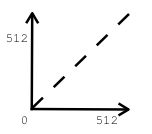
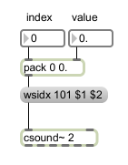
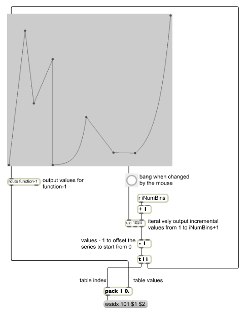
Fortunately the Csound~ object listens to messages preceded by the symbol wsidx, such as �wsidx 1 0 0.01�. These messages allow writing/rewriting values in real-time to predefined function tables, during the Csound performance. The first argument defines the table number, the second declares the index and the third gives the value to be written at that index. In Max we can use a pack object to string the arguments together as shown in Figure 4:
I used Emanuel Jourdan's ej.function.js object to graphically control and write the table values. ej.function is a javascript-based graphic function editor that greatly enhances the features of the original Max function object. One of the benefits of ej.function is that it allows very easy creation of curved segments (alt+drag on a line segment) similar to the function found in automation editing of Logic 8.
After some experimentation it became clear that the best way to get the data out of ej.function for insertion into a Csound function table was to send ej.function incremental x values (integers), starting from 0 and going up to iNumBins (or FFT size/2+1): ej.function outputs an interpolated y value for each input x value, the incremental indexes and y values can then be packed together and sent to csound~ one by one (Figure 5).
We now have a real-time table editor which lets us control the warping function in a very similar way as in FreqWarp. Interestingly in this implementation the user has ultimate control over the curved segments, whereas in the GRM tools version curves are either on or off for all the edited segments.
The remaining additions are mainly feature enhancements and cosmetic embellishments. It is easy enough to calculate the exact frequency value for each bin so that when dragging the mouse on the function editor the user can see the xy frequency values rather than an incoherent bin number. In addition, ej.function has a zoom function that allows zooming in and out of the xy domains, this can be made very intuitive with a little creative programming. Below is a picture of the final interface. Note that it gives access to all the instrument variables including i rate ones (e.g. FFT size, window size, overlap size and window type, Figure 6). There is also a spectral smoothing factor, dry/wet controller and a freeze option for instant freezing of the spectrum. The text field at the button allows the user to enter frequencies by hand, to add points into the function table graph. Another feature is the ability of saving and recalling functions. All of these controllers are real-time, allowing instant audition of the result. Also note that an FFT analyzer has been superimposed onto the table to complete the functionality of the patch (See DspTools.zip for the complete working patch).
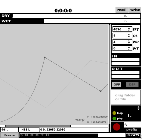
Figure 6: Advanced use of the ej.function Javascript Graphic Function Editor in Max.
Final Remarks
The seamless integration of Csound and Max/MSP gives us the advantage of combing the pros of these powerful languages. Where Csound lacks in graphical interface design, Max can take over, and similarly Csound's flexible and powerful synthesis engine and code based approach can highly simplify, enhance and extend the possibilities of programming with Max/MSP.
What started as an exercise has now developed into a rather elaborate project with the promise of enhancing the usability, controllability and indeed, in my experience so far, stability of the original GRM tools model (note that GRM tools spectral tools do not work at sample rates higher than 48kHz). Judging by ear, there are naturally differences in the sound flavors of the two implementations, no doubt due to the use of different FFT and possibly frequency warping algorithms (I did not have access to the GRM tools code!). However, the comparison is favorable, if not in favor of the current implementation--e.g. less FFT artifacts and blurring effects thanks to the efficient and yet powerful PVS opcodes. In addition, I have almost completed a version of the program that takes advantage of two Csound installations, 32-bit and 64-bit packages, the former used for real-time performance and the later for a double precision render to disk option, both bundled under the same interface. Furthermore, numerous programs are in development to address other rare or esoteric FFT based processes such as an enhanced version of the GRM tools Contrast and an unusual spectral stretching instrument.
References
[1] http://www.grmtools.org/products/stbundle/stbundle.html
[2] The original fsig framework and the earlier PVS opcodes (pvsanal, pvsfread, pvsinfo, pvsynth, pvsadsyn, pvsmaska, pvscross, pvsftw and pvsftr) were created by Richard Dobson and released in Csound 4.13. Victor Lazzarini has since added numerous PVS opcodes in Csound 5 (particularly those discussed here). John Ffitch has also contributed with his pvscent opcodes, although this opcode is not discussed here (for details see http://www.csounds.com/manual/html/SpectralRealTime.html).[3] Davis Pyon - http://www.davixology.com/csound~.html
[4] http://www.csounds.com/udo/displayOpcode.php?opcode_id=10
[5] My thanks to Richard Dobson who suggested this method of dealing with the frequency data on the Csound mailing list.